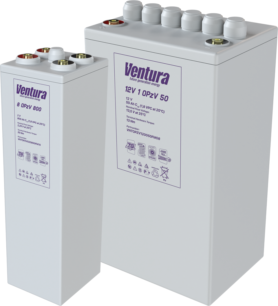
Series and parallel battery connections


 15 min read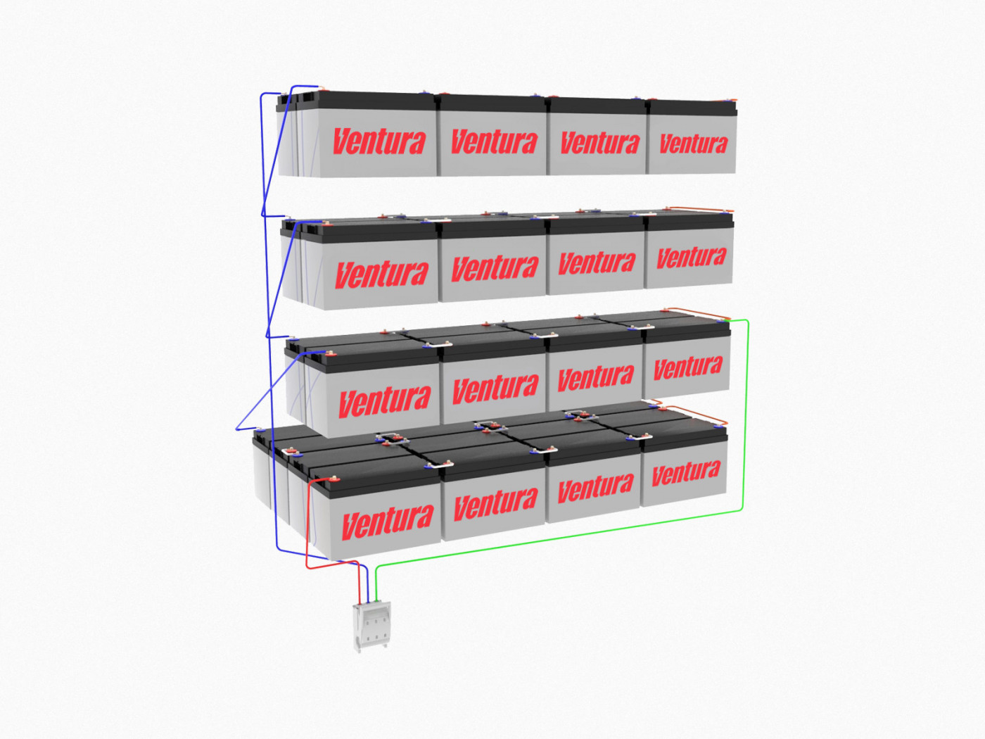
UPS, telecommunications racks and traction systems often require 24-48 V and predictable runtime, so a single battery may not be enough. The problem is solved by combining 12-volt batteries into a block. Choice of connection scheme, serial, parallel or mixed. Parallel-series sequentially sets the operating voltage, available energy reserve, current loads and thermal conditions, and hence the resource. Errors in configuration lead to voltage imbalances, equalizing currents and accelerated wear, but a correctly designed unit ensures stability and safety.
In this article we will tell you how the circuits differ, when to choose which one, how to properly charge batteries in a circuit, and what to pay attention to during installation and operation.
Series connection of batteries
This is a way to assemble a single circuit with a higher voltage from several identical batteries. It is needed when the equipment (UPS, inverter, telecom rack, traction drive) is designed, for example, for a voltage of 24/36/48/80 V. This makes it possible to reduce operating currents, reduce wiring heating and increase operating stability.
Scheme: the “plus” of the first battery is connected to the “minus” of the second, further along the chain. The free “minus” on the far left and the “plus” on the far right are the conclusions of the entire assembly.
What is the output? The voltage is summed (4×12 V - 48 V). The capacity in ampere-hours remains the same as that of one battery of the same model (4 × 12 V 100 Ah - 48 V 100 Ah), the electricity in watt-hours increases due to an increase in voltage.
Does the battery capacity add up when connected in series? No. In a series circuit, the same current flows through all batteries, so the Ah does not add up. The assembly is limited by the capacity of the weakest battery. Only the voltage is summed up, and with it the electricity (Wh).
Advantages of series connection of batteries:
- Less currents at the same power - lower losses on wires, simpler cable sections and switching.
- You can get standard 24/36/48/96 V buses for traction, inverters and UPS.
- Easier to manage large capacities.
Disadvantages and risks:
- The resource and output current will be limited by a battery with a lower actual capacity or higher internal resistance.
- The spread of parameters leads to overcharging of a weak battery when discharged and overcharging when charging.
- The failure of one battery can destroy the entire circuit.
- Chargers with a higher output voltage and an algorithm for a specific type are required (AGM, GEL, FLA, Li-ion, etc.).
The principle of series connection of batteries and what happens inside?
In a series circuit, the same current flows through all the batteries. Each battery's voltage is distributed according to its internal resistance/condition. If one battery “sags” (higher resistance, lower capacity), a large share of the voltage drops on it - it is the first to reach limiting states. This accelerates degradation and leads to a “runaway” in the parameters of the entire circuit.
What happens in a series circuit of different cells
If you put elements of different types, capacities, ages or wear into a series:
- When discharged, a weak battery will go into a deep discharge before the others. In lead-acid, this is sulfation and loss of capacity. In lithium ones, the BMS protection will work (if it exists), or the polarity may be reversed in cells without protection.
- When charging, a weak battery will reach “its” voltage sooner and will actually be recharged (gassing in classic lead-acid batteries with liquid electrolyte, risk of overheating in sealed lead-acid batteries with thickened electrolyte), while the rest of the batteries in the series remain not 100% charged.
- The greater the spread, the faster the distortions grow. As a result, the series loses its resource much earlier than prescribed by the passport.
Accordingly, serial circuits are assembled only from identical batteries of the same manufacturer, series, capacity and approximately the same production date
Why connect cells in series?
This chain is used for the following purposes:
- Reach the standard system voltage of the equipment. Telecom and UPS often operate on 48 V, industrial traction - 24/36/48 V and higher.
- Reduce currents at the same power. Less current means less voltage drop on the cables and less heating of the terminals, more compact switching and higher efficiency.
- Match with a charger/inverter designed for a specific voltage.
Parallel connection of batteries
This method is used when it is necessary to increase the energy storage and available current without changing the operating voltage of the system. Typical cases are 12/24-volt inverters and UPSs, on-board networks of telecom and security systems, where the voltage is set but autonomy is not enough.
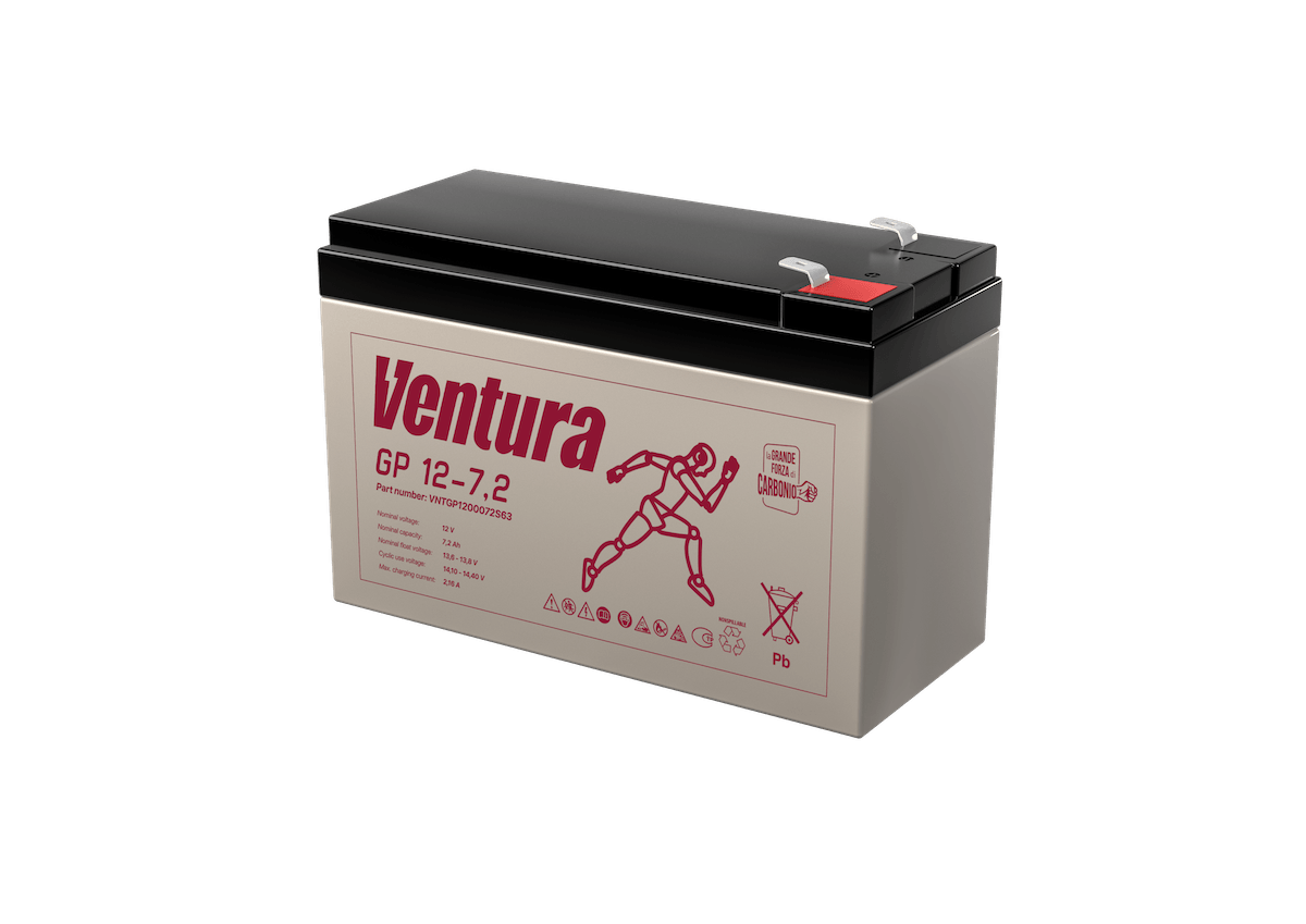
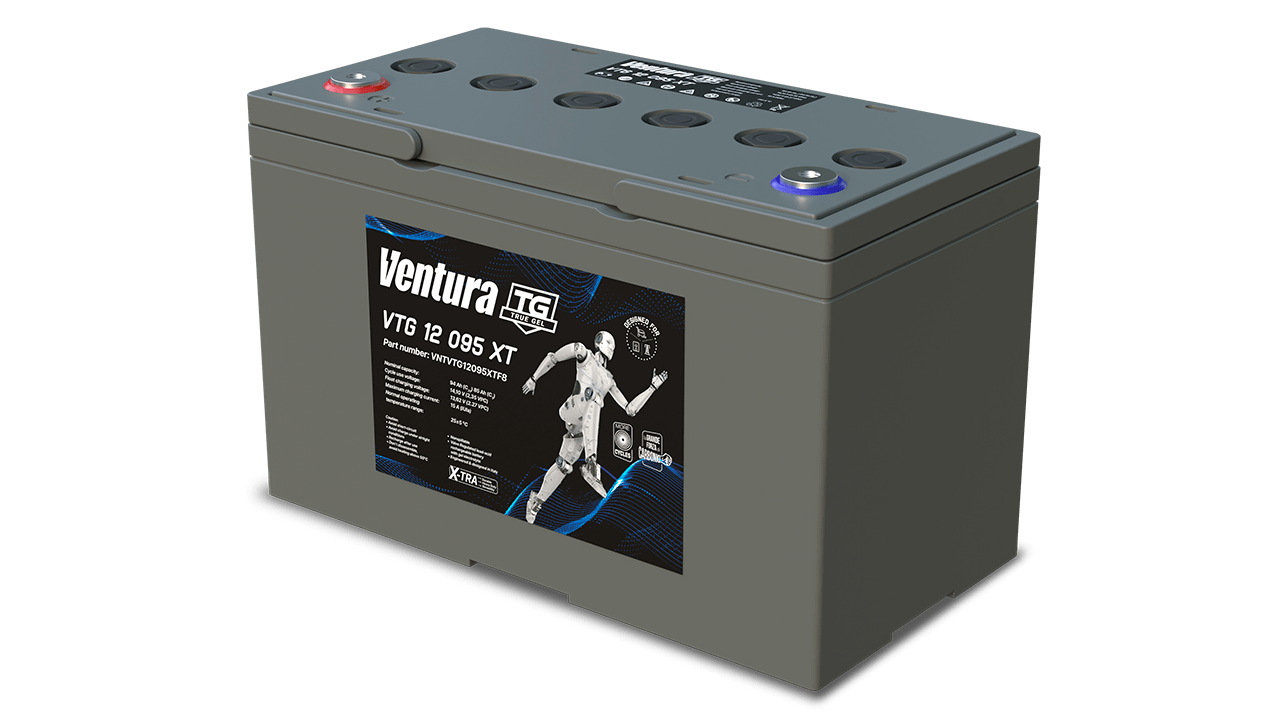
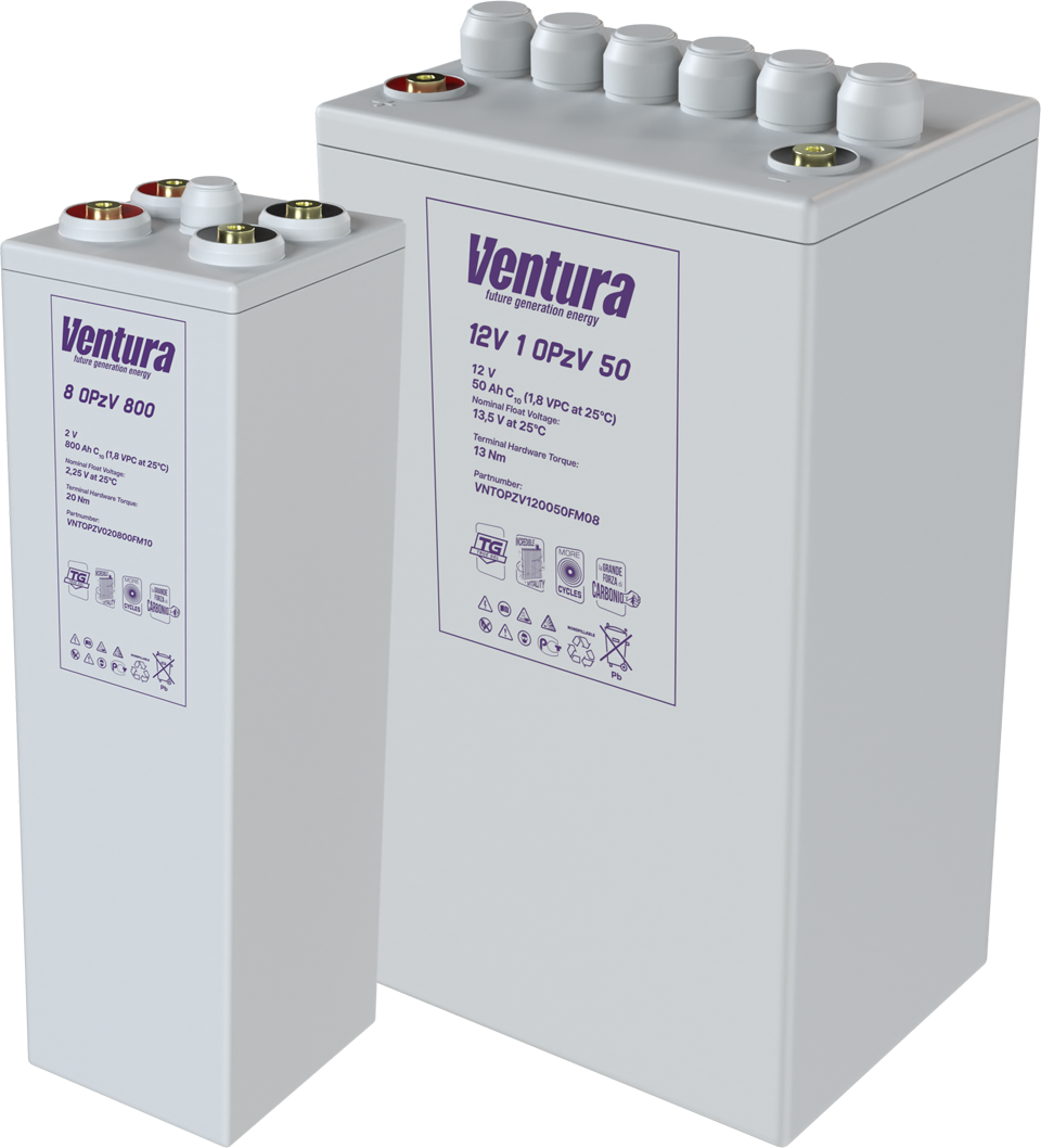
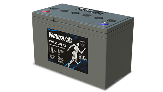
When more 12/24 V autonomy is required, several identical batteries of the same series are used in parallel - this is done with backup AGMs (for example, GP/GPL), and for long cycles - with gel VTG or stationary OPzV from the Ventura catalog.
GP (General Purpose)
Learn more
GP
GPL (General Purpose Longlife)
Learn more
GPL
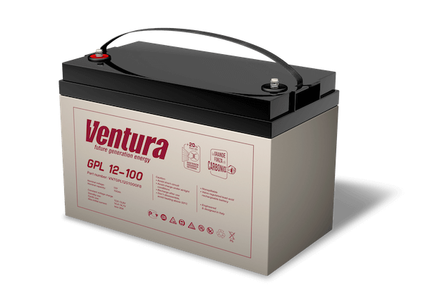
VTG XT (Ventura TRUE GEL X-TRA)
Learn more
VTG XT
OPzV
Learn more
OP zV
With a parallel connection, the voltage remains the same, but the capacity (Ah) and the permissible discharge/starting current are summed up. This allows you to work longer without recharging and tolerate short-term load peaks (starting a compressor, pump) more steadily.
It is important to understand that the current between parallel branches is not divided equally by itself. It is affected by the internal resistance of the batteries and the resistance of the wiring. Therefore, they use identical batteries of the same model and age; before connecting the batteries, they equalize the rest voltage, connect them to common buses symmetrically with cables of the same length and cross-section, and be sure to install a separate fuse/DC circuit breaker on each branch. This reduces the risk of equalizing current surges, overheating and accelerated wear of one of the branches.
Scheme: “plus” to “plus”, “minus” to “minus”. Typically connected via common busbars/terminal blocks. What is the output:
- The voltage does not change: 2×12 V - 12 V.
- Capacity (Ah) and maximum current are summed up: 2 × 12 V 100 Ah - 12 V 200 Ah.
- Electricity (Wh) increases in proportion to the number of parallel branches (due to an increase in capacity).
The advantages of such a chain:
- Longer autonomy at the same voltage.
- You can scale the capacity in steps by adding parallel branches.
- Lower current per battery means its thermal load is reduced.
Disadvantages and risks:
- The currents between the branches are distributed unevenly due to differences in the resistance of the wires and the batteries themselves, which entails accelerated wear of the weak branch.
- When connecting batteries with different quiescent voltages, a surge in the equalizing current (sparking, overheating) is possible.
- Fuses/DC circuit breakers are required for each branch and symmetrical connection to the buses, otherwise one branch will be overloaded.
In practice, they tend to limit the number of parallel branches. The fewer there are, the easier it is to ensure uniformity of currents and condition control.
Parallel-series (mixed) connection
In real projects, it is more common to assemble several identical series circuits (for the required voltage), and then make them parallel (for the required capacitance). Key principles of parallel-series circuit:
- First a series, then a parallel. An assembly of identical batteries of the same model, capacity, age and condition.
- Complete symmetry. Identical lengths and cross-sections of cables from each circuit to the common busbars. The connection is “star”, not “herringbone”.
- Protection of every line. A fuse/breaker on the positive side of each parallel circuit to isolate the fault.
What happens when charging and discharging
With a series connection, during charging, the current source sees the sum of the voltages. The current passes through all batteries the same. Without monitoring individual parts, some batteries will not be fully charged/overcharged. In practice, it is important to use chargers with a temperature sensor and, if possible, mid-circuit monitoring or a balancer. For sealed gel batteries, increased equalizing voltages are not allowed; for AGM batteries, they are allowed only according to the manufacturer’s instructions.
During discharge, the current is the same, the voltage is distributed unevenly. It is necessary to control the minimum voltage of the entire circuit and, preferably, each link/section in order to prevent deep overdischarge of a weak battery.
In a parallel connection, when charging, the current is divided between the branches. To avoid equalizing current surges, do not directly connect batteries with different quiescent voltages. First, they are brought to similar voltage/charge values, then connected in parallel.
During discharge, the currents of the branches depend on the resistance of the paths. The correct star and identical cables help equalize the load. Each branch has its own fuse.
Key considerations
In order for the chain to work predictably without loss of resource, it is enough to adhere to the following rules:
- In one assembly there are only identical batteries by type, model, capacity, age and condition. Mixing AGM, GEL, FLA, Li-ion, etc. is not allowed.
- Preliminary preparation. Before parallel connection, equalize the voltage and charge.
- Wiring symmetry. Equal lengths and cross-sections of cables to common busbars, star connection.
- Fuse or DC circuit breaker for each parallel circuit, polarity marking, short circuit protection.
- Clean terminals, correct tightening torque, anti-corrosion protection.
- All batteries in the assembly must operate at the same temperature. Local overheating should be avoided.
- Use chargers with the ability to set a profile for the selected battery type.
- Regularly check quiescent voltage, internal resistance/conductivity, temperature, and, if possible, check the middle of the circuit and balance.
- Limiting parallel branches. The fewer parallel lines, the easier it is to ensure current uniformity and control. In UPS/telecom practice, they usually tend to fit into several identical circuits instead of a fan of many heterogeneous ones.
- Work must be performed on disconnected, protected circuits, wearing personal protective equipment, without sparking, and also comply with the manufacturer’s requirements.
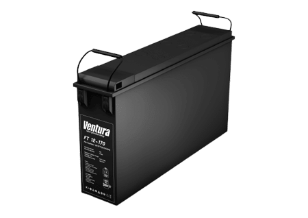
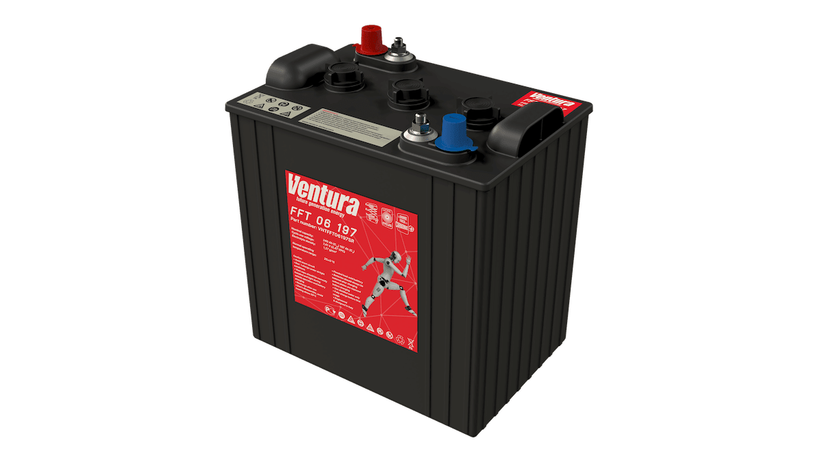
It is optimal to choose serial solutions for a specific task. For 48 V cabinets - AGM front-terminal FT, for high discharge currents in the UPS - HR/HRL, for long cycles and increased durability - TRUE GEL VTG or OPzV, for traction - FFT (FLA) and other traction series. Current models with all characteristics are presented in the catalog. This makes it easier to immediately compare voltage, capacity, dimensions and operating mode with the requirements of your system.
GP (General Purpose)
Learn more
GP
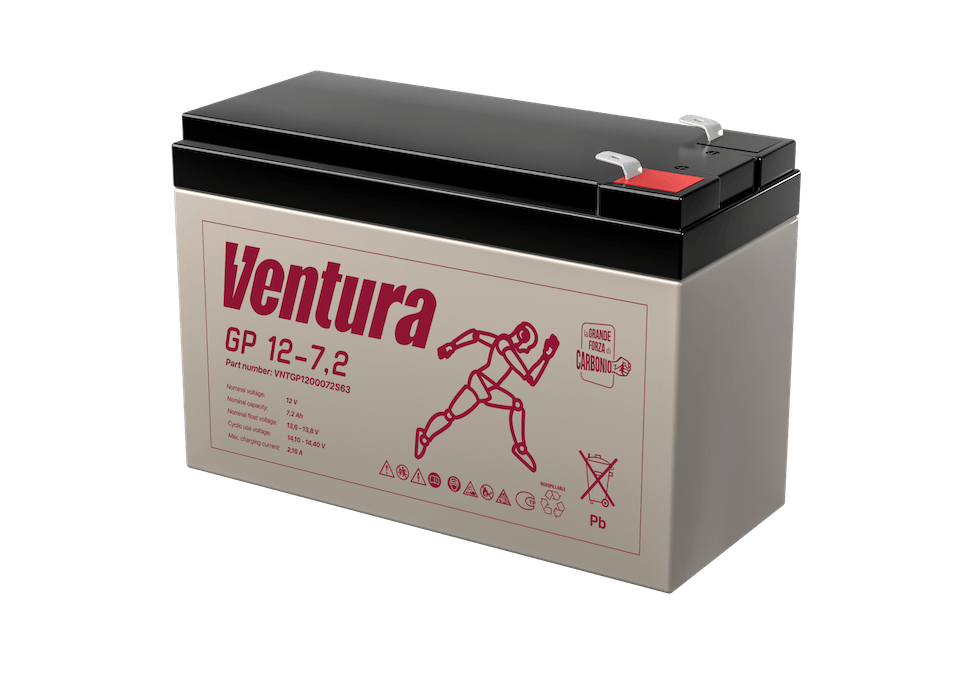
GPL (General Purpose Longlife)
Learn more
GPL
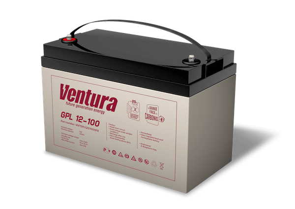
HR (High Rate)
Learn more
HR
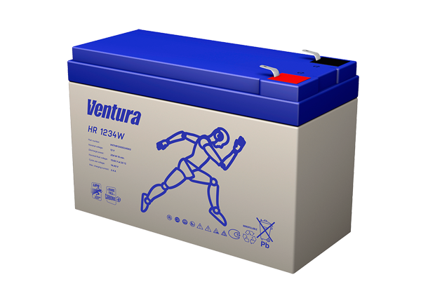
HRL (High Rate Longlife)
Learn more
HRL
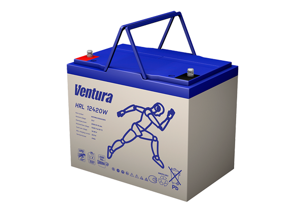
FT (Front Terminal)
Learn more
FT
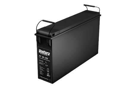
FFT (Flooded Flat Traction)
Learn more
FFT
VTG XT (Ventura TRUE GEL X-TRA)
Learn more
VTG XT
OPzV
Learn more
OP zV