How to charge an AGM battery correctly: voltage, current, chargers, and other considerations


 1 min read
The design of an AGM battery imposes strict charging requirements: correct voltage and current settings directly affect capacity, cycle life, and the battery’s readiness for operation.
This article explains the technical aspects of AGM technology, charging requirements, charger selection criteria, and practical recommendations for industrial operation of Ventura batteries.
What is an AGM battery and how does AGM technology work?
AGM stands for Absorbent Glass Mat, a technology using an absorbent fiberglass separator. The electrolyte is not free-flowing: it is held entirely within porous fiberglass mats between the plates. This creates a sealed design and eliminates maintenance such as adding water or checking the electrolyte level.
Gas recombination inside the case reaches 99% or more, allowing the battery to operate in any position except upside down. AGM batteries have significantly lower internal resistance than conventional flooded batteries, providing high peak discharge current and stable power delivery under sudden loads.
AGM battery features
The main design feature of AGM batteries is the tight compression of the plates against the fiberglass separator. This reduces internal resistance, improves contact between active materials, and increases specific power. A sealed VRLA (Valve Regulated Lead Acid) valve controls pressure inside the case for safe operation at different currents.
Most industrial AGM batteries operate from -20 to +60 °C, although the optimal range is +20 to +25 °C. Outside this range, capacity and service life change according to the temperature coefficients specified in the manufacturer’s technical documentation.
Advantages of AGM batteries
Industrial AGM batteries are maintenance-free, requiring neither water refills nor periodic electrolyte density measurements. They deliver high specific power, reaching 300 W/kg or more for the HRL and HR series, and offer long service life: 5 to 12 years in float operation and up to 15 years for Ventura PRO. Standard form factors and terminals ensure compatibility with industrial equipment from leading UPS manufacturers. The sealed case and gas recombination valve allow safe installation in enclosed technical rooms.
A low self-discharge rate of no more than 2–3% of rated capacity per month at +20 °C allows the battery to be stored for 6–12 months without recharging. This is particularly useful for warehouse reserves and spare-parts inventories at infrastructure facilities.
What makes Ventura AGM batteries unique (GFC and SOI technologies)?
Ventura Battery uses patented manufacturing technologies that distinguish its products from standard AGM batteries. GFC (La Grande Forza di Carbonio) technology adds carbon to the active material of the negative plates. This improves conductivity, accelerates charge acceptance, and provides stable current output over repeated charge and discharge cycles.
SOI (Sostanza Organica Interna) technology introduces a special organic substance into the positive electrodes. Combined with GFC, it protects the active material against shedding, maintains rated capacity throughout the specified service life, and broadens the operating-current range. Developed with these technologies, the Ventura GPL series is intended for UPS, telecommunications, and backup power systems requiring predictable, stable battery performance over the facility’s entire design life.
Where are AGM batteries used?
Ventura AGM batteries cover a wide range of industrial and infrastructure applications:
- UPS and backup power systems: offices, banks, server rooms, and continuously operating facilities.
- Data centers: providing runtime until the diesel generator starts.
- Telecommunications: base stations, switching nodes, and fiber-optic networks.
- Medical equipment: ventilators, operating tables, and mobile diagnostic systems.
- Fire and security systems: fire alarms, access control, and video surveillance.
- Power and energy storage: substations, solar installations, and wind power systems.
- Transport and warehouse infrastructure: material-handling vehicles and warehouse management systems.
How does an AGM battery differ from a standard lead-acid battery?
A conventional flooded lead-acid (FLA) battery contains liquid electrolyte between its plates. During charging, electrolytic dissociation splits water into hydrogen and oxygen, producing substantial gas emissions. The gases escape through vent plugs, so distilled water must be added periodically and the battery room must be ventilated.
An AGM battery is a sealed VRLA design. Its electrolyte is held in a nonwoven fiberglass mat, gases recombine inside the case, and no maintenance is required. The key differences between the technologies are shown below:
| Parameter | FLA (flooded) | AGM (VRLA) |
| Electrolyte | Free-flowing liquid | Held in the mat |
| Maintenance | Required (water refilling) | Not required |
| Gas emissions | Significant | Minimal (>97–99% recombination) |
| Peak discharge current | Moderate | High |
| Internal resistance | Higher | Lower |
| Permitted orientation | Upright only | Any position except upside down |
| Service life (float) | 3–5 years | 5–12+ years |
For industrial applications where reliability, compact size, and maintenance-free operation are critical, AGM is the de facto standard in the VRLA segment.
Why do AGM batteries require special charging conditions?
The sealed design of AGM batteries imposes strict charging requirements. Unlike flooded batteries with liquid electrolyte, their ability to release gas is limited. The VRLA valve opens only when operating pressure is exceeded, so charging settings must prevent excessive gas generation, which directly affects long-term battery life.
For this reason, both charging voltage and maximum charging current are specified for AGM batteries. The charging mode depends on the application: float mode is used for UPS and stationary systems, while cycle mode is used for traction and standalone applications. The manufacturer defines limits for each mode that must be observed when selecting and configuring charging equipment.
What current and voltage are permitted when charging an AGM battery?
The manufacturer specifies the correct charging parameters in the technical documentation for each series. The following values apply to Ventura industrial AGM batteries:
Float mode for UPS and stationary systems:
- Charging voltage: 2.27 V/cell, or 13.6 V for a 12 V battery at +25 °C.
- Charging current: the initial current is limited to no more than 0.25C–0.3C to prevent overheating, then decreases automatically.
Cycle mode for standalone and traction applications:
- Charging voltage: 2.35–2.45 V/cell, or 14.1–14.7 V for a 12 V battery depending on the series, such as 14.1–14.4 V for GPL and up to 14.7 V for HRL.
- Initial charging current: no more than 0.25C, where C is the rated capacity in Ah. The maximum current for a 100 Ah battery is 25 A.
Temperature compensation is mandatory: for every 10 °C decrease, the charging voltage of a 12 V battery should be increased by approximately 0.3 V. Most modern industrial chargers support automatic temperature compensation.
Which chargers are suitable for AGM batteries?
Industrial AGM batteries require specialized microprocessor-controlled chargers supporting VRLA/AGM profiles. The main requirements are:
- IUoU support: a three-stage or multistage algorithm with current limiting and transition to maintenance float voltage.
- Output voltage accuracy within ±1% of the set value.
- Temperature compensation that automatically adjusts charging voltage according to battery temperature.
- Protection against short circuits, overheating, reverse polarity, and deep discharge.
- Output current within the manufacturer’s recommended range for the specific series.
For data centers, telecommunications nodes, and server rooms, industrial chargers with integrated monitoring and control over SNMP, Modbus, or CAN bus are optimal. These devices provide real-time current and voltage monitoring, event logging, and integration with facility management systems.
How to charge an AGM battery correctly: step-by-step instructions
These instructions apply to Ventura industrial AGM batteries used with a professional charger supporting VRLA/AGM.
Step 1. Check the battery condition. Before charging, measure the open-circuit voltage (OCV). A fully charged 12 V AGM battery reads 12.6–12.8 V, while a partially discharged battery reads 12.0–12.5 V.
Step 2. Configure the charger. Select the AGM or VRLA profile and set the charging voltage according to the manufacturer’s documentation. For Ventura GPL, use 14.1–14.4 V in cycle mode; for HRL, use 14.4–14.7 V. The float range is the same for both series: 13.5–13.8 V. Set the maximum current to no more than 0.25C of rated capacity.
Step 3. Connect the charger. Connect the charger terminals to the battery, positive first and then negative. Make sure both connections are secure.
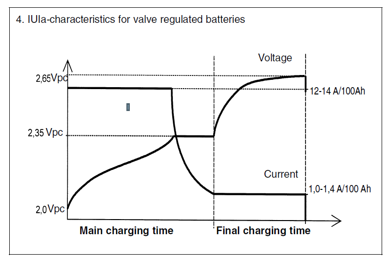
Step 4. Main charging phase (CC: constant current). The charger supplies constant current. Voltage gradually rises as the battery charges, while current remains stable until the set threshold is reached.
Step 5. Transition to constant voltage (CV). At the threshold voltage, the charger switches to CV mode. Current continues to decrease as the battery reaches full charge. This phase ends when current falls to 0.01–0.02C.
Step 6. Transition to float charging. After the main charging cycle, the charger automatically lowers the voltage to the float level, keeping the battery charged without overcharging.
Step 7. Disconnect the charger. When charging is complete, disconnect the negative terminal and then the positive terminal. Let the battery rest for 15–30 minutes before measuring OCV and putting it into service.
Charging recommendations for Ventura HRL AGM batteries
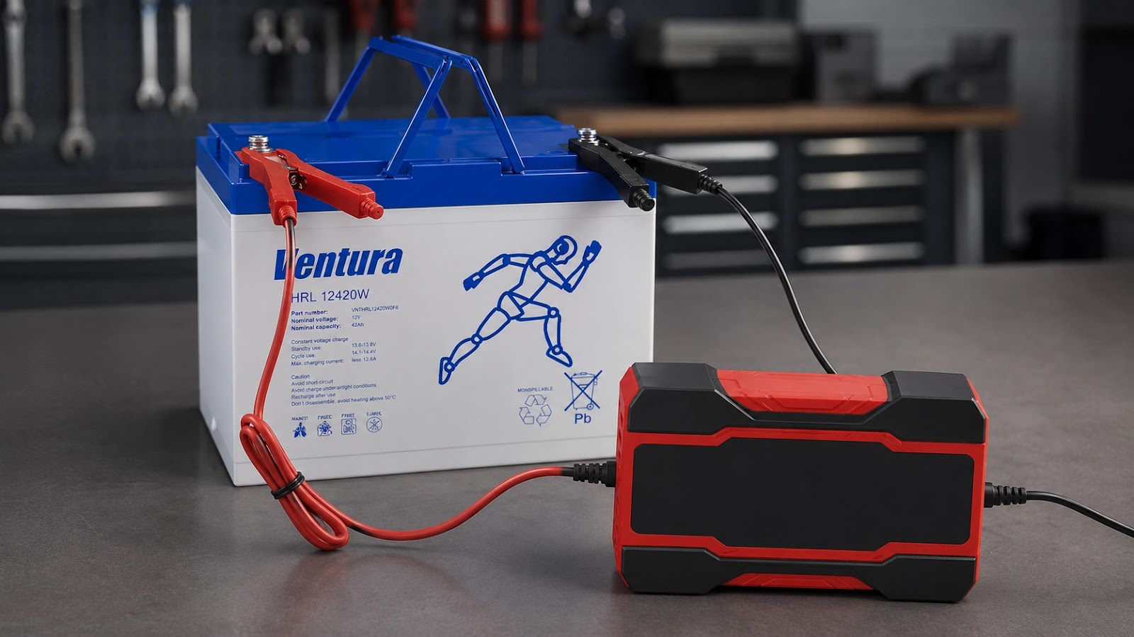
Ventura HRL (High Rate Long Life) batteries are high-specific-power industrial AGM batteries developed for UPS systems and data centers. Their design is optimized for high discharge currents over short runtimes of 5–15 minutes at loads of 100 W per cell or more. GFC and SOI technologies provide stable discharge current and a predictable charging curve throughout the specified service life.
For correct Ventura HRL charging, observe these parameters: float mode at 2.275 V/cell, or 13.65 V at +25 °C; cycle mode at 2.45 V/cell, or 14.7 V; maximum initial charging current of 0.25C; and temperature compensation of -3 mV/°C per cell. Recharge every six months when stored at +20 °C and every three months above +30 °C. Ventura HRL batteries are compatible with standard industrial UPS rectifiers.
Conclusion
Ventura industrial AGM batteries provide reliable operation wherever power stability is critical. Selecting the correct charging mode is essential to long-term battery system reliability. Professional chargers supporting AGM/VRLA profiles, the recommended current and voltage settings, and proper temperature compensation preserve the battery throughout its service life.
Frequently asked questions
How can I tell when an AGM battery is fully charged?
Charging current is the main indicator. During the final CV phase, current falls to 0.01–0.02C. For a 100 Ah battery, this means 1–2 A at stable voltage. After a 30-minute rest, a fully charged 12 V battery has an open-circuit voltage of 12.6–12.8 V. Professional chargers complete the cycle automatically.
How can I extend the service life of an AGM battery?
To achieve the full design life, follow the manufacturer’s charging requirements for voltage, current, and temperature compensation, and keep the battery room at +18 to +25 °C. Use certified chargers with an AGM/VRLA profile, periodically check battery-block voltage and internal resistance, and recharge batteries promptly during long-term storage or standby operation.
Can an AGM battery be charged with a conventional charger?
A charger without an AGM/VRLA profile and multistage algorithm is not recommended for Ventura industrial batteries. Conventional fixed-voltage chargers that do not transition to float mode cannot complete the charging cycle correctly. Professional IUoU chargers maintain precise settings at every stage and protect battery life.
What voltage is used to charge a 12 V AGM battery?
For 12 V Ventura industrial AGM batteries at +25 °C, cycle-mode voltage is typically 14.1–14.7 V depending on the series, while float voltage is 13.5–13.8 V. Always consult the technical documentation for the exact series values. Temperature compensation is required when the operating temperature differs from +25 °C.
How long does an AGM battery take to charge?
Charging time depends on depth of discharge, battery capacity, and selected current. At 0.1C, or 10% of capacity, a full cycle takes 10–14 hours. At 0.2C, it takes 6–8 hours. An initial current of up to 0.25C may be used for faster capacity recovery. Exact charging time depends on charger characteristics and the preceding depth of discharge.
Can an AGM battery remain on continuous charge?
Yes. This is the normal float operating mode for AGM batteries in UPS systems. With the correct float voltage and temperature compensation, continuous charging does not reduce battery life. Most industrial UPS systems manage this function automatically, keeping the battery ready for use.
What should I do after an AGM battery is deeply discharged?
When the open-circuit voltage of a 12 V battery is below 10.5 V, use a recovery mode with a reduced initial current of 0.01–0.05C until voltage reaches 11.0–11.5 V, then run a standard charging cycle. Professional chargers with a desulfation function perform this process automatically.